
A power transformer is one of the most valuable and critical assets in any electrical power system. Whether installed in an industrial manufacturing plant, utility substation, renewable energy project, or commercial facility, transformers operate continuously to transfer electrical energy safely and efficiently between voltage levels. However, transformers are also exposed to electrical faults, overloads, insulation deterioration, overheating, lightning surges, and mechanical failures that can lead to catastrophic damage if not detected in time.
A transformer failure is rarely limited to the transformer itself. It can interrupt production, damage connected equipment, increase maintenance costs, create fire hazards, and result in prolonged outages. This is why every medium and large power transformer requires a well-designed transformer protection system capable of detecting abnormal operating conditions and isolating faults before they develop into major failures.
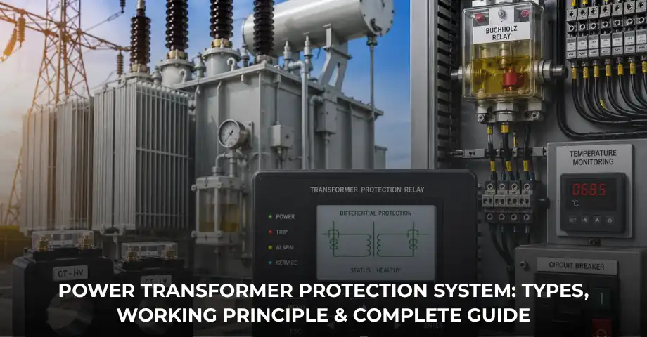
Modern transformer protection is no longer based on a single protective relay. Instead, it combines instrument transformers, intelligent protection relays, current transformers, circuit breakers, temperature monitoring devices, and multiple protection functions that work together to provide fast and reliable protection.
In this comprehensive guide, you’ll learn how a transformer protection system works, the different types of transformer protection, common transformer faults, protection relays used in industrial applications, and best practices for selecting an effective protection scheme.
Expert Insight: In modern industrial substations, transformer failures are rarely caused by a single fault. Most major failures begin as minor electrical or thermal abnormalities that remain undetected. A properly coordinated transformer protection system identifies these early warning signs and isolates the transformer before irreversible damage occurs.
What Is a Transformer Protection System?
A transformer protection system is a combination of protective devices, measuring equipment, and control systems designed to monitor the operating condition of a transformer and disconnect it from the electrical network whenever unsafe or abnormal conditions occur.
Its primary objective is not only to protect the transformer itself but also to safeguard the entire electrical system connected to it. A properly designed protection system detects both internal and external faults, allowing protective devices to isolate only the affected transformer while keeping the remainder of the electrical network in service.
Depending on transformer size, voltage level, and application, a protection system may include:
- Current transformers (CTs)
- Potential transformers (PTs)
- Differential protection relays
- Overcurrent relays
- Earth fault relays
- Buchholz relays
- Temperature monitoring devices
- Pressure relief devices
- Circuit breakers
- Alarm and trip circuits
These components work together to continuously monitor electrical, thermal, and mechanical conditions inside the transformer.
Why Do Power Transformers Need Protection?
Power transformers represent a significant investment for any industrial facility or utility. Depending on their capacity, replacement costs can range from several lakhs to several crores of rupees, not including production losses caused by downtime.
A comprehensive transformer protection system provides several important benefits.
Protects High-Value Equipment
Transformers are expensive assets with long replacement lead times. Early fault detection helps prevent extensive damage to windings, insulation, and the transformer core.
Improves Personnel Safety
Transformer failures may result in arc flashes, oil fires, explosions, or high-energy electrical faults. Protective relays reduce these risks by disconnecting the transformer quickly.
Minimises Production Downtime
Industrial plants depend on continuous power. Rapid fault isolation reduces production losses and speeds up maintenance activities.
Protects Connected Equipment
A transformer fault can affect motors, switchgear, generators, variable frequency drives, and sensitive automation equipment. Proper protection limits fault propagation throughout the system.
Enhances Grid Reliability
In substations and utility networks, transformer protection helps maintain stable power distribution by isolating only the faulted equipment.
Common Faults in Power Transformers
Before selecting a protection scheme, it is important to understand the different types of transformer faults. Protection relays are configured to detect these faults as early as possible.
1. Internal Faults
Internal faults occur inside the transformer and are among the most dangerous because they can rapidly damage windings and insulation.
Common internal faults include:
- Inter-turn winding faults
- Phase-to-phase faults
- Phase-to-earth faults
- Core insulation failure
- Winding insulation breakdown
- Tap changer faults
Internal faults are primarily detected using differential protection and Buchholz relays.
2. External Faults
External faults occur outside the transformer but can still subject it to extremely high fault currents.
Examples include:
- Short circuits on outgoing feeders
- Distribution system faults
- Busbar faults
- Cable faults
Protection against these faults is commonly provided by overcurrent and earth fault relays.
3. Overload Conditions
Continuous loading beyond the transformer’s rated capacity increases winding temperature and accelerates insulation ageing. While temporary overloads may be acceptable, prolonged overloading significantly reduces transformer life.
4. Earth Faults
Earth faults occur when a live conductor comes into contact with earth or grounded metal parts. These faults may initially carry relatively low current but can quickly develop into severe internal failures if left unprotected.
5. Overheating
Transformer overheating may result from:
- Cooling fan failure
- Pump malfunction
- Blocked radiators
- Overloading
- High ambient temperatures
Temperature protection plays an important role in preventing insulation deterioration.
6. Oil Leakage and Gas Formation
Oil-immersed transformers depend on insulating oil for cooling and dielectric strength. Internal faults can produce gas within the transformer tank, while oil leakage reduces insulation performance.
These abnormal conditions are typically detected by Buchholz relays and oil level monitoring devices.
Main Components of a Transformer Protection System
An effective transformer protection system consists of several interconnected devices, each performing a specific protective function.
Current Transformers (CTs)
Current transformers continuously measure primary current and provide scaled secondary current signals to protection relays.
The performance of the entire protection scheme depends heavily on proper CT selection. Choosing the correct Current Transformer Accuracy Class ensures that relays receive accurate current information during both normal operation and fault conditions.
If you’re new to instrument transformers, our guide on CT vs PT (Current Transformer vs Potential Transformer) explains the different roles of current and voltage transformers in protection systems.
Protection Relays
Protection relays act as the brain of the transformer protection system. They continuously analyse electrical parameters and determine whether operating conditions remain within safe limits.
Modern substations increasingly use numerical protection relays because they provide multiple protection functions, event recording, self-diagnostics, communication capabilities, and programmable settings within a single device.
For a detailed overview of relay technologies, you can also explore our guide to transformer protection relays.
Circuit Breakers
When a relay detects a fault, it sends a trip command to the circuit breaker. The breaker disconnects the transformer from the electrical network, preventing further damage.
Reliable circuit breakers are therefore essential for effective transformer protection.
Alarm and Trip Circuits
Alarm circuits provide early warning of abnormal conditions such as rising oil temperature or low oil level, while trip circuits automatically disconnect the transformer when critical fault thresholds are exceeded.
Types of Transformer Protection
No single protection method can safeguard a transformer against every possible fault. Modern transformer protection systems therefore combine multiple protection functions to provide complete coverage.
Differential Protection
Differential protection is considered the primary protection for medium and large power transformers.
It compares the current entering the transformer with the current leaving it. Under normal operating conditions, these currents should be nearly equal after accounting for transformer ratio and vector group.
If a significant difference exists, the relay interprets it as an internal fault and immediately trips the associated circuit breaker.
Differential protection offers:
- Fast fault detection
- High sensitivity
- Selective operation
- Protection against internal winding faults
- Reduced equipment damage
Overcurrent Protection
Overcurrent protection serves as both primary and backup protection depending on transformer size and application.
It detects current levels exceeding preset limits and trips the transformer if abnormal conditions persist.
Industrial facilities commonly use inverse-time overcurrent relays to coordinate transformer protection with feeder protection systems.
For a deeper understanding, read our guide on Overcurrent Protection, which explains relay characteristics, working principles, and industrial applications.
Earth Fault Protection
Earth faults are among the most common electrical faults in power transformers. They occur when a live conductor or transformer winding comes into contact with earth due to insulation failure, moisture ingress, cable damage, or deterioration of insulating materials.
Although earth faults may initially produce relatively low fault currents, they can quickly develop into severe internal faults if not cleared promptly. Earth fault protection relays continuously monitor zero-sequence current and initiate a trip whenever current exceeds the configured setting.
Earth fault protection is commonly used in:
- Power transformers
- Distribution transformers
- Industrial substations
- Incoming feeders
- Motor control centres
Restricted Earth Fault (REF) Protection
Restricted Earth Fault (REF) protection is a specialised protection scheme designed to detect earth faults within a defined zone of the transformer winding. It provides much higher sensitivity than conventional earth fault protection and is particularly effective for detecting low-level winding faults close to the neutral point.
REF protection operates using current transformers installed on both the phase conductors and neutral conductor. By comparing these current values, the relay can identify even minor internal earth faults while remaining stable during external faults.
Large industrial transformers and utility substations frequently use REF protection alongside differential protection to achieve comprehensive internal fault coverage.
Buchholz Relay Protection
The Buchholz relay is one of the most important protective devices used in oil-immersed transformers equipped with a conservator tank. Unlike electrical protection relays, the Buchholz relay responds to gas generation and oil movement inside the transformer.
Minor internal faults gradually decompose transformer oil and insulation, producing gases that accumulate inside the relay chamber. When sufficient gas collects, the relay operates an alarm contact, allowing maintenance personnel to investigate before a major failure occurs.
During severe internal faults, rapid oil movement activates the trip mechanism, immediately disconnecting the transformer.
Buchholz protection offers several advantages:
- Early fault detection
- Detection of insulation deterioration
- Identification of winding faults
- Protection against oil-related failures
- Reduced risk of catastrophic transformer damage
Temperature Protection
Transformer insulation life is directly affected by operating temperature. Excessive winding or oil temperature accelerates insulation ageing and significantly reduces transformer life expectancy.
Temperature protection systems continuously monitor:
- Top oil temperature
- Winding temperature
- Cooling system performance
- Ambient temperature
If temperature exceeds preset limits, alarms are generated. If overheating continues, the protection system trips the transformer to prevent permanent damage.
Pressure Relief Protection
Internal faults may generate excessive pressure inside the transformer tank. Pressure relief devices safely release pressure before it reaches dangerous levels, reducing the likelihood of tank rupture or explosion.
Many modern transformers combine pressure relief devices with alarm contacts, enabling operators to investigate abnormal conditions immediately.
Overflux Protection
Overfluxing occurs when the ratio of voltage to frequency (V/f) exceeds the transformer’s design limit. Excessive magnetic flux increases core losses, resulting in overheating and possible insulation damage.
Numerical relays monitor voltage and frequency continuously to protect transformers against overfluxing conditions.
Transformer Protection Relay Types
Modern transformer protection systems typically employ several relay functions rather than relying on a single protective device.
| Protection Relay | Primary Function | Typical Application |
|---|---|---|
| Differential Relay | Detects internal winding faults | Main transformer protection |
| Overcurrent Relay | Detects overloads and external faults | Backup protection |
| Earth Fault Relay | Detects earth leakage currents | Ground fault protection |
| Restricted Earth Fault Relay | Sensitive internal earth fault detection | Large power transformers |
| Buchholz Relay | Gas detection and oil surge monitoring | Oil immersed transformers |
| Temperature Relay | Monitors winding and oil temperature | Thermal protection |
How a Transformer Protection System Works
Although individual protection devices perform different tasks, they operate together as an integrated protection scheme.
The sequence typically follows these steps:
- Current transformers continuously measure transformer current.
- Protection relays analyse electrical parameters such as current, voltage, temperature, differential current, and earth fault current.
- If any parameter exceeds the configured protection settings, the relay identifies the fault type.
- The relay immediately sends a trip command to the associated circuit breaker.
- The circuit breaker isolates the transformer from the power system.
- Alarm systems notify operators, allowing maintenance personnel to investigate and rectify the fault.
This coordinated operation limits equipment damage while maintaining the reliability of the remaining electrical network.
Applications of Transformer Protection Systems
Transformer protection systems are used wherever reliable electrical power is critical.
Industrial Manufacturing Plants
Factories rely on transformer protection to safeguard production equipment and minimise downtime.
Power Generation Plants
Generating stations integrate transformer protection with generator protection relays to provide comprehensive protection for generating units.
Utility Substations
Substations use multiple protection functions to maintain reliable transmission and distribution of electrical energy.
Steel Plants
Steel manufacturing facilities operate high-capacity transformers under demanding conditions that require robust protection schemes.
Cement Plants
Continuous process industries such as cement manufacturing depend on reliable transformer operation to avoid costly production interruptions.
Mining Operations
Mining sites frequently experience harsh operating environments where transformer protection plays an important role in maintaining electrical safety.
Best Practices for Maintaining Transformer Protection Systems
Even the most advanced protection system requires periodic inspection and testing to maintain reliability.
Recommended maintenance activities include:
- Routine relay testing and calibration
- Current transformer ratio verification
- Inspection of secondary wiring connections
- Transformer oil testing and dissolved gas analysis
- Thermal imaging inspections
- Circuit breaker maintenance and functional testing
- Verification of alarm and trip circuits
- Review of relay event records and fault history
Preventive maintenance significantly reduces the likelihood of unexpected transformer failures.
Common Mistakes in Transformer Protection Design
Many transformer failures are not caused by equipment defects but by poor protection system design or incorrect relay settings.
Common mistakes include:
- Selecting the wrong current transformer ratio.
- Ignoring Current Transformer Accuracy Class requirements.
- Improper differential relay settings.
- Poor coordination between relays and circuit breakers.
- Failure to test protection relays periodically.
- Ignoring temperature monitoring devices.
- Inadequate protection redundancy.
- Lack of preventive maintenance.
Frequently Asked Questions
What is a transformer protection system?
A transformer protection system is a coordinated combination of protective relays, current transformers, circuit breakers, monitoring devices, and alarm systems designed to detect transformer faults and disconnect the transformer before major damage occurs.
Why is differential protection used for transformers?
Differential protection provides fast and highly sensitive detection of internal transformer faults by comparing current entering and leaving the transformer.
Which relay is mainly used for transformer protection?
Differential relays serve as the primary protection for most medium and large power transformers, while overcurrent, earth fault, Buchholz, and temperature relays provide additional protection.
What are the most common transformer faults?
Common faults include winding faults, insulation failure, earth faults, overheating, overloading, oil leakage, and external short circuits.
How often should transformer protection systems be tested?
Protection relays, current transformers, trip circuits, and associated protection equipment should be inspected and tested periodically according to manufacturer recommendations and industry maintenance practices.
Conclusion
A reliable transformer protection system is essential for ensuring the safe, efficient, and uninterrupted operation of power transformers. Modern protection systems combine differential protection, overcurrent protection, earth fault protection, Buchholz relays, temperature monitoring, and intelligent numerical relays to detect a wide range of electrical and mechanical faults.
Rather than relying on a single protective device, today’s industrial substations use coordinated protection schemes that integrate instrument transformers, numerical protection relays, and circuit breakers to minimise equipment damage, improve personnel safety, and maximise system reliability.
Whether protecting a distribution transformer in a manufacturing plant or a large power transformer in a utility substation, selecting the appropriate protection philosophy is critical for long-term operational reliability.
At Delta Technocrats, we specialise in advanced transformer protection solutions, protection relays, current transformers, circuit breakers, and complete industrial power protection systems. Our experienced team helps industries, utilities, and infrastructure projects select reliable protection solutions tailored to their operational requirements, ensuring improved safety, reduced downtime, and dependable electrical system performance.