
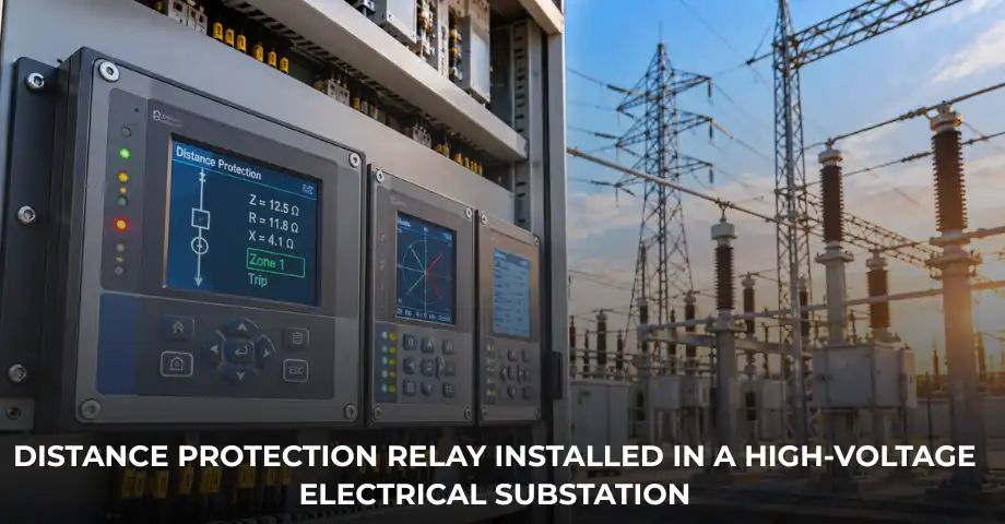
Distance protection is an important protection method used for high-voltage transmission and sub-transmission lines. Unlike conventional overcurrent protection, a distance protection relay does not rely only on current magnitude to determine whether a fault exists within its protection area. Instead, it evaluates the apparent impedance seen from the relay location using measured voltage and current.
This approach is particularly useful where fault current can change with generation levels, network configuration and source impedance. Modern distance relays can combine phase and earth-fault distance elements with directional logic, multiple protection zones, communication-assisted tripping, load-encroachment supervision and power-swing functions.
For industrial substations, utility networks and transmission applications, understanding how a distance protection relay works is important when selecting protection equipment, developing relay settings and coordinating adjacent protection systems.
What Is a Distance Protection Relay?
A distance protection relay is a protective device that estimates the apparent impedance between its installation point and a fault. Because the impedance of a transmission line is related to its electrical characteristics and length, the measured impedance provides an indication of whether a fault lies within a defined protection zone.
The relay does not literally measure physical distance in kilometres. Instead, it calculates electrical impedance, normally expressed in ohms, from voltage and current measurements and compares that value with its configured operating characteristics.
If the measured impedance falls inside the configured protection characteristic and the required directional and supervisory conditions are satisfied, the relay can issue a trip command according to the applicable zone and time delay.
Why Is Distance Protection Used?
Fault current does not remain constant throughout an electrical network. It can change when generators are connected or disconnected, transformers operate in parallel, network topology changes or the utility source strength varies.
Overcurrent protection mainly responds to current magnitude. Distance protection adds another measurement relationship by considering voltage and current together to determine apparent impedance.
This makes distance protection particularly suitable for transmission and sub-transmission lines. Multiple zones can provide fast primary protection together with delayed backup coverage beyond the protected line.
Distance protection can therefore be useful where maintaining fast and selective line protection is important. However, the final protection method and settings must always be established from the actual network characteristics and protection study.
How Does a Distance Protection Relay Work?
The basic operating principle involves measuring voltage and current, calculating apparent impedance and comparing the result with the relay’s protection characteristic.
Voltage and Current Measurement
A voltage transformer, potential transformer or capacitive voltage transformer provides a scaled representation of system voltage to the relay, while a current transformer provides a proportional current signal.
Impedance Calculation
A simplified relationship between voltage, current and impedance is:
Z = V / I
For an illustrative calculation, assume a relay measures 66 kV and 1,000 A:
Z = 66,000 / 1,000 = 66 Ω
The simplified apparent impedance is therefore 66 Ω on the stated measurement basis. Actual distance-relay calculations use appropriate phase-to-phase or phase-to-earth loop quantities, instrument-transformer ratios and relay algorithms. This example is only intended to explain the concept and must not be treated as an actual relay setting.
Zone Comparison
The calculated impedance is compared with the configured distance characteristic. If the measured point falls within the applicable zone and the required directional and supervisory conditions are satisfied, the relay initiates the corresponding protection action.
IEC 60255-121 addresses functional and performance requirements for distance-protection functions, including impedance-plane characteristics, phase selection, directionality, starting and time-delay characteristics.
Role of CTs and PTs/VTs in Distance Protection
Distance protection depends heavily on accurate voltage and current inputs. The CT provides the current measurement, while the PT or VT provides the voltage measurement used with current to calculate apparent impedance.
CT ratio, accuracy, burden and performance can affect the current signal. Similarly, the PT or VT ratio, connection, accuracy and voltage-signal integrity affect the relay’s measurement.
Delta Technocrats already explains these fundamentals in its guide to CT vs PT: Current Transformer vs Potential Transformer, so this article does not repeat the complete instrument-transformer theory.
In high-voltage applications, capacitive voltage transformers can also have transient-response characteristics that affect the voltage signal during certain fault conditions. Engineers therefore need to consider the behaviour of the voltage-measurement system when evaluating distance protection performance.
Distance Protection Zones
One of the defining features of distance protection is the use of multiple zones. Each zone covers a different portion of the network and normally operates with its own reach and timing.
Zone 1
Zone 1 normally provides the fastest protection for the protected line. A common engineering practice is to set its reach to approximately 80–90% of the protected line impedance so that the relay provides fast protection without unnecessarily reaching into the adjacent line.
This 80–90% range is not a universal setting. The actual reach depends on line data, instrument-transformer errors, modelling accuracy, fault resistance, protection philosophy and the requirements of the specific network.
Zone 2
Zone 2 extends beyond the Zone 1 reach. It can cover the remaining portion of the protected line and provide backup coverage for part of the adjacent section. Because it reaches farther, it normally operates with a time delay so that protection at the remote end has an opportunity to clear a fault first.
Zone 3
Zone 3 can provide further backup coverage into the adjacent network and normally operates with a longer delay than Zones 1 and 2. Modern numerical relays can provide several configurable zones, so the exact arrangement depends on the protection philosophy and network design.
Illustrative Zone Example
Consider a hypothetical high-voltage line connecting Substation A and Substation B. A distance relay at Substation A may use Zone 1 for fast protection over most of the A–B line, Zone 2 for the remaining line section and part of the next section, and Zone 3 for additional backup coverage.
If a fault occurs close to Substation A, Zone 1 may provide the fastest operation. A fault farther along the line may fall into Zone 2 and receive delayed protection. If protection at another location fails, a suitably configured backup zone may provide additional coverage.
The actual impedance reach and time delays must be calculated from the line and adjacent-network impedances. The example is intended only to explain the protection concept.
Types of Distance Relay Characteristics
Mho Characteristic
The mho characteristic appears as a circular characteristic on the impedance plane and can provide directional behaviour when appropriately polarised. It has historically been widely used for transmission-line protection.
One consideration is resistive-fault coverage. Depending on the characteristic and application, a mho element may provide less resistive coverage than a quadrilateral characteristic.
Quadrilateral Characteristic
A quadrilateral characteristic provides greater independent control over resistive and reactive reach. This can make it useful where engineers need greater coverage for faults with significant resistance.
However, increasing resistive reach can introduce security concerns if heavy-load conditions and load encroachment are not properly considered.
| Parameter | Mho Characteristic | Quadrilateral Characteristic |
|---|---|---|
| Operating shape | Circular | Quadrilateral |
| Directional behaviour | Can provide inherent directional behaviour when appropriately polarised | Directional supervision depends on relay design and application |
| Resistive-fault coverage | Can be more limited | Greater independent resistive reach |
| Typical consideration | Directional security and line applications | Flexibility for resistive faults |
| Main concern | Resistive coverage in some applications | Load encroachment and security |
Impedance and Reactance Characteristics
Impedance and reactance characteristics have also been used in different distance-protection applications. Their suitability depends on the network, line characteristics, fault resistance and relay design.
Distance Relay Settings: Key Parameters
Distance-relay settings require accurate line impedance data, CT and VT ratios, source impedance, system configuration and fault-study results. Important parameters include zone reach, zone timing, earth-fault compensation, resistive reach, load encroachment and power-swing logic.
| Setting Parameter | Purpose |
|---|---|
| Zone reach | Defines the impedance range covered by each protection zone. |
| Zone time delay | Supports coordination with remote and adjacent protection. |
| Earth-fault compensation | Accounts for zero-sequence impedance in earth-fault measurement. |
| Resistive reach | Determines the intended coverage for resistive faults. |
| Load encroachment | Helps prevent inappropriate operation under heavy-load conditions. |
| Power-swing logic | Helps distinguish system swings from genuine faults. |
For earth faults, engineers also need to consider positive- and zero-sequence impedances and the relay’s earth-fault compensation method. The correct values depend on the actual line and network configuration.
Distance Protection for Phase and Earth Faults
Distance relays can provide separate protection elements for phase faults and earth faults. Phase-distance protection evaluates appropriate phase-to-phase quantities, while earth-fault distance protection uses phase-to-earth measurement relationships and compensation for the network’s zero-sequence characteristics.
An earth fault can therefore produce a different apparent impedance from a phase fault. A phase-distance setting should not simply be assumed to provide the correct earth-fault reach.
Load Encroachment and Power Swings
A distance relay must distinguish genuine faults from system conditions that can move the measured impedance toward the protection characteristic.
During heavy power transfer, the apparent load impedance can enter an area close to the distance characteristic. Load-encroachment logic can help restrict operation in defined load regions.
Power swings create another challenge because the apparent impedance can move across the impedance plane during a system disturbance. Power-swing detection and blocking functions can help prevent inappropriate distance trips while maintaining protection for genuine faults.
Communication-Assisted Distance Protection
Distance protection can operate without a communication channel, but communication can improve the speed and selectivity of line-protection schemes.
Modern schemes can exchange information between both ends of a protected line. Depending on the scheme, this communication can support permissive or blocking logic and accelerate clearing for faults within the protected line.
Therefore, communication is not an absolute requirement for distance protection, but it can be valuable where fast and selective line protection is required.
Distance Protection vs Overcurrent Protection
| Parameter | Distance Protection | Overcurrent Protection |
|---|---|---|
| Main measurement | Voltage and current relationship | Current magnitude |
| Protection quantity | Apparent impedance | Current |
| Typical application | Transmission and sub-transmission lines | Feeders, transformers, motors and distribution systems |
| Protection arrangement | Multiple impedance zones | Pickup and time/current characteristics |
| Communication | Can be used in advanced line schemes | Not always required |
These functions can complement each other. Distance protection may provide primary line protection while overcurrent or other protection functions provide additional backup.
Delta Technocrats covers overcurrent protection separately, providing a deeper explanation of current-based protection principles.
Distance Protection in Industrial and Utility Substations
Distance protection is strongly associated with transmission and sub-transmission line protection, but it can also be evaluated for suitable industrial networks with appropriate voltage levels, line characteristics and system configurations.
For example, consider a large industrial plant with several substations connected through high-voltage feeders and a utility interconnection. If fault-current levels vary substantially with the plant’s operating configuration, engineers may evaluate distance protection as part of the line-protection strategy rather than relying only on current-based protection.
The objective would be to determine whether impedance-based protection can provide the required speed, selectivity and backup coverage. It should not be assumed that distance protection is automatically suitable for every industrial plant; the decision requires a project-specific protection study.
Delta Technocrats’ product range includes protective relays for line, cable, transmission-line and distribution-line applications, along with control and relay panels incorporating distance protection for line panels.
Common Distance Protection Challenges
Fault resistance: Resistive faults can cause the measured impedance to differ from the expected line impedance and may challenge protection reach.
Heavy loading: High power transfer can move the apparent impedance toward the protection characteristic, requiring appropriate loadability assessment.
Power swings: System disturbances can move measured impedance across the impedance plane, making power-swing supervision important in suitable applications.
Voltage-transformer problems: Voltage-circuit failures can distort impedance calculations. Voltage supervision can help reduce inappropriate operation caused by measurement problems.
Mutual coupling, series compensation, changing network topology and inverter-based resources can introduce additional application considerations. These conditions require project-specific engineering rather than generic relay settings.
How Engineers Apply Distance Protection in a Real Project
Engineers begin with the latest single-line diagram and accurate network data. They determine positive- and zero-sequence line impedances, CT and VT ratios, source impedances and maximum and minimum fault conditions.
They then define the protection philosophy and calculate zone reaches and operating times. Phase and earth-fault behaviour, fault resistance, loadability, power swings and remote-end protection are also evaluated where applicable.
Finally, engineers document relay-setting calculations, impedance characteristics, fault analysis and coordination results. The proposed settings should undergo the applicable engineering review before implementation. Testing and commissioning should follow approved site procedures and be carried out by qualified personnel.
Distance Protection and Numerical Relays
Modern distance protection is commonly implemented through numerical relays. These devices can combine distance elements with overcurrent, earth fault, breaker supervision, fault recording, communication and other functions.
However, a numerical relay does not remove the need for proper engineering. Instrument-transformer inputs, system modelling, impedance calculations, zone reach, coordination and protection logic still need to be verified.
For broader information about relay technologies, see Delta Technocrats’ Numerical vs Conventional Protection Relays.
Frequently Asked Questions About Distance Protection Relays
What is the main function of a distance protection relay?
Its main function is to detect faults by evaluating the apparent impedance between the relay location and the fault and determining whether the fault falls within a configured protection zone.
What is the difference between Zone 1, Zone 2 and Zone 3?
They generally provide progressively wider protection coverage with different operating times. Zone 1 is normally the fastest, while Zones 2 and 3 provide progressively extended and delayed backup coverage. Actual reach and timing depend on the protection study.
Why is distance protection used for transmission lines?
It can provide impedance-based protection that remains useful when fault-current magnitude varies with network configuration and source conditions. Multiple zones can also provide fast primary protection and delayed backup.
What is the difference between mho and quadrilateral characteristics?
Mho characteristics are circular on the impedance plane and can provide inherent directional behaviour when appropriately polarised. Quadrilateral characteristics provide greater flexibility in resistive reach but require careful consideration of loadability and security.
Can distance protection operate without communication?
Yes. A distance relay can operate using local voltage and current measurements. Communication-assisted schemes are additional arrangements that can improve speed or selectivity for particular line-protection applications.
Strengthen High-Voltage Line Protection with Delta Technocrats
Distance protection requires more than selecting a relay with a distance function. Accurate line impedance data, CT and VT inputs, fault studies, zone calculations and system operating conditions all influence the final protection scheme.
Delta Technocrats works across electrical protection, high-voltage equipment, substations, protection relays, control and substation automation. Its product range includes protective relays and control panels incorporating distance protection for line applications.
For industrial and utility projects involving high-voltage line protection, relay upgrades, protection panels or related substation requirements, Delta Technocrats can support a project-specific approach based on the electrical system and protection objectives.
Conclusion
A distance protection relay uses voltage and current measurements to calculate apparent impedance and determine whether a fault lies within a defined protection zone. This makes distance protection an important technique for transmission and sub-transmission line protection.
Zone 1, Zone 2 and Zone 3 provide different layers of protection, while mho and quadrilateral characteristics allow engineers to address different network and fault conditions. At the same time, fault resistance, load encroachment, power swings, CT performance and voltage-measurement behaviour require careful consideration.
Modern numerical distance relays add communication, monitoring and supervision functions, but these features still depend on accurate system data and sound protection engineering. For high-voltage line and substation projects, the appropriate distance-protection scheme should therefore be established through a detailed study rather than generic relay settings.