
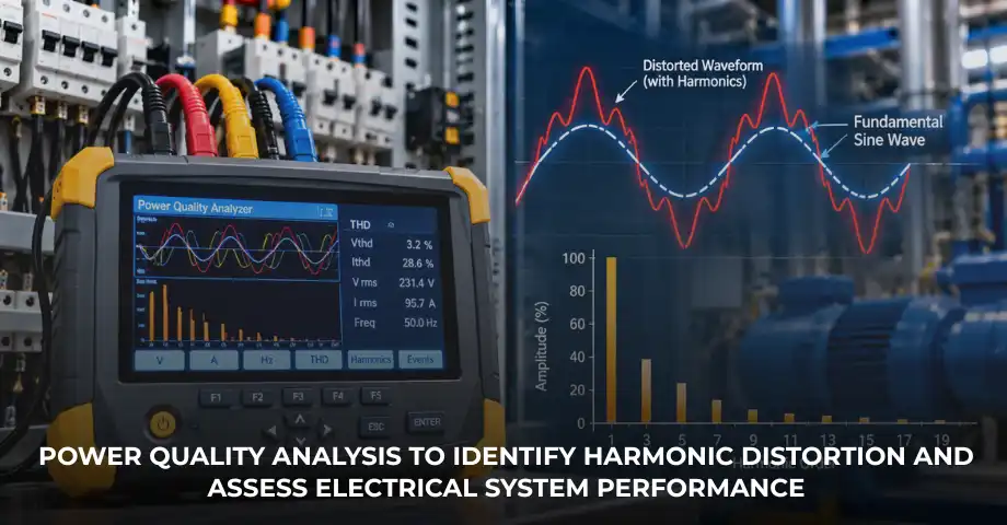
Total harmonic distortion (THD) is an important power-quality indicator in industrial electrical systems. It measures the harmonic content of a voltage or current waveform relative to its fundamental component. Excessive distortion can contribute to transformer heating, motor losses, capacitor-bank problems and unreliable operation of sensitive equipment.
Industrial facilities commonly meet harmonics from variable-frequency drives (VFDs), rectifiers, uninterruptible power supplies (UPS) and other nonlinear loads. Finding these sources is only the first step. Engineers must also measure distortion accurately, read the results against applicable standards and decide whether mitigation is needed.
This guide explains the THD formula, common causes, effects on industrial equipment, measurement steps, IEEE 519-2022 voltage distortion limits, the difference between THD and total demand distortion (TDD), and what to consider when selecting harmonic filters.
What is total harmonic distortion?
THD measures the combined RMS magnitude of the included harmonic components relative to the fundamental-frequency component of a waveform. It is normally expressed as a percentage.
In a 50 Hz system, the fundamental frequency is 50 Hz. Harmonics occur at whole-number multiples of it:
Nonlinear loads can draw current in pulses instead of following a smooth sine wave. These currents add harmonics to the network and can distort voltage as they interact with system impedance.
There are two principal forms of THD:
Voltage THD (THDv)
Measures harmonic voltage components relative to the fundamental voltage.
Current THD (THDi)
Measures harmonic current components relative to the fundamental current.
THDi helps engineers assess current waveform distortion, while THDv shows voltage waveform distortion at the measurement point. Both are useful, but they are not interchangeable. For a broader introduction to harmonic sources and effects, see our guide to harmonic distortion in industrial power systems.
How is total harmonic distortion calculated?
The general THD formula compares the root-sum-square value of the included harmonic components with the magnitude of the fundamental component.
Here, V₁ and I₁ are the RMS fundamental voltage and current. Vₕ and Iₕ are the RMS values of the matching harmonic components. The harmonic orders included depend on the measurement method and assessment requirements.
Practical calculation example
Suppose a hypothetical voltage measurement records a fundamental of 230 V, a third harmonic of 6 V, a fifth harmonic of 8 V and a seventh harmonic of 4 V.
The calculated THDv is about 4.68% for the components included in this simplified example. It is not a complete standards-compliance result, because other harmonic orders and the applicable measurement procedure have not been considered. The example shows why engineers must examine the harmonic components, not only the fundamental voltage, when judging waveform quality.
Common causes of THD in industrial systems
Variable-frequency drives
VFDs control the speed of motors in pumps, fans, compressors and conveyors. Many conventional drives use a rectifier to convert incoming AC into DC before generating a controlled output for the motor. The input rectifier can draw nonsinusoidal current and introduce harmonics.
In a typical three-phase six-pulse rectifier, the fifth and seventh harmonics are often significant. The actual spectrum depends on drive design, operating load, supply characteristics and installed mitigation equipment.
Consider a plant with several VFD-controlled motors across its production line. Each drive contributes harmonic currents according to its design and operating conditions. At the common supply connection, these currents combine with contributions from other loads. Some components may reinforce one another, while others may partly cancel.
So engineers cannot work out a plant’s overall distortion by simply adding the THDi percentages shown by individual drives. They need to assess the combined harmonic spectrum at the relevant measurement point under representative operating conditions.
Rectifiers and UPS systems
Rectifiers in battery chargers, DC power supplies and industrial conversion equipment can contribute harmonic currents. UPS systems may also add distortion depending on their rectifier and inverter design, input filtering and connected loads. Modern equipment may include power-factor correction or active input stages, so its real contribution should be established by measurement, not assumption.
Other nonlinear loads
Switching power supplies, welding equipment, electronic lighting, induction heating systems and other power-electronic devices can also add to harmonic distortion. Their impact depends on equipment design, loading, operating schedules and the network. For an accurate assessment, consider which loads run at the same time and how the harmonic spectrum changes through the production cycle.
Effects of excessive harmonic distortion
Transformer heating and losses
Harmonic currents can increase transformer winding losses and stray losses. Some losses are more sensitive to frequency than ordinary resistive losses, which can raise temperature and reduce available capacity under certain operating conditions.
For example, a transformer feeding several industrial drives carries both fundamental and harmonic currents. If the extra losses push temperatures above expected levels, engineers may need to assess loading, transformer design, harmonic spectrum and temperature records. THD alone cannot show whether a transformer is overheating or what its remaining capacity is. Condition data can support this investigation. Delta Technocrats discusses the role of transformer condition monitoring in assessing transformer performance.
Capacitor-bank resonance
Capacitor banks are widely used for reactive power compensation. However, capacitors interact with the inductance of transformers, cables and the wider network. Under certain conditions, this can create a resonant frequency near a harmonic frequency present in the system.
For example, a plant may add power-factor correction capacitors while running several nonlinear loads. If the network creates an unfavourable resonance, harmonic current and voltage may be amplified, increasing stress on capacitors and related components. This is a potential risk, not an inevitable outcome. A proper engineering assessment should establish whether resonance is likely and whether mitigation is needed. See our guide to automatic power factor correction panels.
Motor and equipment performance
Harmonic voltages and currents can increase motor losses, add heating and create torque pulsations under certain conditions. Electronic equipment may also have operating problems if voltage distortion affects its power supply or control circuits. The impact varies with equipment design, harmonic spectrum and operating conditions.
Harmonics may also affect some measurement and protection arrangements. If unusual relay operation or measurement discrepancies occur, investigate the complete electrical system rather than assuming harmonics are the only cause. Where operating conditions need to be viewed alongside power-quality data, SCADA for electrical substations can support monitoring and alarms, depending on the installed configuration.
How to measure total harmonic distortion
1. Select the correct measurement point
Choose the measurement point according to the purpose of the assessment. Measurements at an individual VFD can help investigate that drive’s behaviour, while measurements at the point of common coupling (PCC) can support installation-level assessments against applicable utility interface limits. Distortion inside a facility may differ from distortion at the PCC because harmonic contributions can interact and partly cancel. These points should not be treated as interchangeable.
2. Use a suitable power quality analyser
A power quality analyser can capture voltage and current waveforms, calculate harmonic components and report THDv and THDi. Depending on its features, it may also record individual harmonic magnitudes, frequency, power factor and voltage events. Confirm that the instrument supports the required harmonic orders, measurement intervals and reporting functions. For a formal standards-based assessment, verify the instrument and method against the applicable requirements.
3. Check instrument ratings and safety
Use voltage probes, leads and inputs rated for the electrical system and measurement category. Current clamps, probes or current transformers must suit the expected current and relevant frequency range. Confirm phase identification, connection configuration and instrument settings before recording.
Measurements on live industrial equipment should be done only by suitably trained and authorised personnel using appropriate protective equipment and site safety procedures. Never use unsuitable leads or sensors just because the analyser can display THD values.
4. Record representative operating conditions
THD can vary with load level, production schedules and the combination of equipment running at a given time. Record relevant conditions, including which major loads are running and whether the plant is operating normally.
A single reading can point to a potential concern, but a formal assessment may need measurements over defined intervals and across representative operating conditions. Use the evaluation periods and statistical methods required by the applicable standard when judging compliance.
5. Examine individual harmonic orders
THD gives one combined percentage but does not show which harmonic orders dominate. Two installations can have the same THD and different harmonic spectra. Reviewing individual harmonic magnitudes helps engineers trace likely sources and assess possible interactions with transformers, capacitors and other network components.
IEEE 519-2022 and acceptable THD levels
IEEE Std 519-2022, IEEE Standard for Harmonic Control in Electric Power Systems, sets harmonic distortion limits for applicable steady-state assessments at the PCC. These are not universal operating limits for every item of equipment or every internal bus in an industrial installation. The values below are examples from the standard’s PCC voltage distortion limits table:
| Bus voltage at the PCC | Individual harmonic voltage limit (h ≤ 50) | Total voltage THD limit |
|---|---|---|
| V ≤ 1 kV | 5.0% | 8.0% |
| 1 kV < V ≤ 69 kV | 3.0% | 5.0% |
For the voltage distortion table, IEEE 519-2022 considers integer harmonic frequencies through the 50th order. This does not mean every THD measurement, under every standard or purpose, must use the same harmonic range.
IEC 61000-4-7 addresses instrumentation and measurement of harmonics and interharmonics, while IEC 61000-4-30 addresses power-quality measurement methods. Their relevance and applicable editions should be checked against the particular assessment. Do not assume every measurement requires the same instrument class or procedure.
A single instantaneous THD reading is not enough to establish full compliance where the standard requires defined measurement intervals and statistical evaluation. Consult the applicable edition of the complete standard and relevant utility requirements before making a compliance decision.
Reference: IEEE Std 519-2022 – IEEE Standard for Harmonic Control in Electric Power Systems.
THD vs TDD: understanding the difference
THDi and total demand distortion (TDD) both describe harmonic current, but they use different reference values. THDi compares the RMS sum of the included harmonic currents with the fundamental current at the time of measurement. TDD compares it with the maximum demand load current, IL, established at the PCC for the applicable assessment.
Here, I₂, I₃ and the other terms are RMS harmonic current components. IL is the maximum demand load current established under the applicable standard and assessment. H is the highest harmonic order included under the applicable method.
For example, suppose an installation has a fundamental current of 40 A and a combined RMS harmonic current of 8 A. Its THDi is 20%. If the established maximum demand load current is 100 A, its TDD is 8%.
| THDi | TDD | |
|---|---|---|
| Reference current | Fundamental current at the time of measurement | Maximum demand load current (IL) at the PCC |
| Behaviour at low load | Can rise when fundamental current is low | Uses a fixed demand-current reference |
| Typical use | Waveform distortion at a point | Installation-level PCC assessment |
THDi can rise when the fundamental load current becomes low, even if the absolute harmonic current has not increased in proportion. TDD provides a demand-current reference for the installation-level assessment. IEEE 519 current limits depend on factors such as system voltage and the ratio of short-circuit current at the PCC to maximum demand load current. There is no single universal TDD limit for all installations.
How can industrial plants reduce harmonic distortion?
Active harmonic filters
Active harmonic filters measure selected harmonic current components and inject compensating current to reduce distortion within their design and operating limits. Their suitability depends on the harmonic spectrum, load variation, required compensation and system configuration. Learn more about active harmonic filters for industrial power quality.
Passive filters and detuned capacitor banks
Passive filters use combinations of inductors, capacitors and sometimes resistors to provide a path for selected harmonic frequencies. Their design must consider the target harmonics, source impedance, changing loads and possible resonance.
Where reactive power compensation is needed, detuned capacitor-bank arrangements may help reduce the risk of problematic resonance under specified design conditions. Power-factor correction does not automatically eliminate harmonic distortion, so capacitor-bank design should account for the actual electrical environment.
Carry out a system study before selecting a filter
Filter selection should be based on measured harmonic spectra, voltage and current loading, operating scenarios, transformer and cable characteristics, capacitor banks and system impedance. Where necessary, harmonic studies and resonance analysis can help compare possible solutions.
Frequently asked questions about total harmonic distortion
1. What does total harmonic distortion measure?
THD measures the combined RMS magnitude of the included harmonic components relative to the fundamental component of a voltage or current waveform.
2. What is the difference between THDv and THDi?
THDv measures voltage harmonic distortion, while THDi measures current harmonic distortion. They describe different aspects of power quality.
3. What causes high THD in industrial plants?
Common contributors include VFDs, rectifiers, UPS systems, switching power supplies and other nonlinear loads. Their impact depends on equipment design, operating conditions and network characteristics.
4. What is an acceptable THD level?
There is no single universal limit for every installation. Applicable PCC limits, equipment requirements and the relevant standard should guide the assessment.
5. How is THD measured?
A suitable power quality analyser measures waveform components and calculates THD. Correct instrument ratings, safe connections and an appropriate measurement method are essential.
6. Is TDD the same as THDi?
No. THDi uses fundamental current as its reference, whereas TDD uses the maximum demand load current established for the applicable PCC assessment.
7. Can an active harmonic filter reduce THD?
An appropriately selected active harmonic filter can reduce selected harmonic currents. Its effectiveness depends on measured harmonics, loading, system characteristics and correct installation.
Improve industrial power quality with Delta Technocrats
Understanding total harmonic distortion helps industrial facilities assess waveform quality, identify dominant harmonic components and decide whether further investigation or mitigation is needed.
For plants operating drives, rectifiers, capacitor banks and other nonlinear equipment, a structured assessment can guide decisions about active harmonic filters, passive filtering, power-factor correction and monitoring. The right solution depends on measured electrical conditions and the requirements of the installation.
Delta Technocrats works in electrical engineering, including substation solutions, power-quality systems, protection and monitoring. Contact the team to discuss your industrial electrical requirements and identify an appropriate engineering approach for your application.