
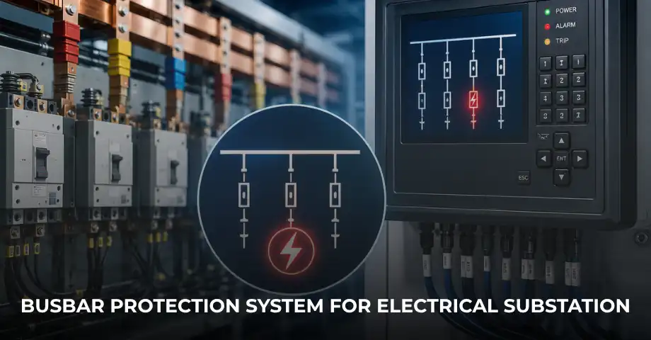
Busbars are among the most critical components of an electrical power system, serving as the common connection point for incoming and outgoing feeders, transformers, generators, and other electrical equipment within a substation or switchgear. Because multiple circuits are connected to a single busbar, any fault occurring on the busbar can disrupt power supply to an entire section of the electrical network and cause extensive equipment damage if it is not cleared immediately.
A Busbar Protection System is specifically designed to detect internal faults occurring within the busbar protection zone and isolate the affected section of the electrical system within milliseconds. Modern protection schemes use advanced numerical relays and differential protection principles to provide high-speed, selective, and reliable fault detection while maintaining the stability of the remaining electrical network.
Busbar protection systems are widely used in power generation plants, transmission substations, distribution substations, industrial facilities, steel plants, cement plants, renewable energy installations, and other critical electrical infrastructure where uninterrupted power supply is essential.
In this guide, you’ll learn what a Busbar Protection System is, how it works, its major components, different protection methods, and why it is an essential part of modern substation protection.
What Is a Busbar Protection System?
A Busbar Protection System is a specialised electrical protection scheme designed to detect and isolate faults occurring within a defined busbar protection zone. It continuously monitors the current flowing into and out of the busbar using Current Transformers (CTs). Under normal operating conditions, the total incoming current equals the total outgoing current. If an internal fault develops, this current balance is disturbed, and the protection relay immediately trips the associated circuit breakers.
Unlike feeder protection or transformer protection, which safeguard individual equipment, busbar protection secures the common electrical connection that links multiple circuits together. Because a busbar fault can interrupt several feeders or transformers simultaneously, rapid fault isolation is essential to minimise equipment damage and maintain system stability.
Modern numerical busbar protection systems use sophisticated algorithms to distinguish genuine internal faults from external faults, CT saturation, and switching transients, ensuring dependable operation under all operating conditions.
Quick Definition
A Busbar Protection System continuously compares the current entering and leaving a busbar. If an internal fault causes a current imbalance, the protection relay instantly trips the connected circuit breakers to isolate the faulty busbar section.
Busbar protection is an important part of a comprehensive electrical protection strategy. To understand how it fits into an overall protection philosophy, read our guide on Transformer Protection System.
Why Busbar Protection Is Important
Busbars act as the central distribution point within substations and switchgear. Since numerous circuits are connected to the same busbar, even a single internal fault can interrupt power to multiple feeders, transformers, generators, or industrial loads.
Without dedicated busbar protection, fault currents may continue flowing until backup protection operates, increasing the risk of equipment damage, prolonged outages, and safety hazards.
Busbar Protection Systems provide:
- Fast fault detection.
- Selective fault isolation.
- Improved system reliability.
- Reduced equipment damage.
- Enhanced personnel safety.
- Reduced outage duration.
- Improved power system stability.
- Protection of high-value substation assets.
Because busbar faults typically involve very high fault currents, protection systems are designed to operate within a few milliseconds, significantly limiting thermal and mechanical stress on electrical equipment.
Working Principle of a Busbar Protection System
The most widely used busbar protection scheme is based on the principle of differential protection. Current Transformers installed on every incoming and outgoing circuit continuously measure the current entering and leaving the busbar.
During normal operation:
- Total Incoming Current = Total Outgoing Current
- Differential Current ≈ Zero
- Protection Relay Remains Stable
If an internal fault occurs within the busbar protection zone:
- Incoming Current ≠ Outgoing Current
- Differential Current Increases
- The Protection Relay Detects the Imbalance
- All Associated Circuit Breakers Trip Instantly
The relay operates only for faults located inside the defined protection zone, ensuring excellent selectivity while remaining stable during external faults.
Example of Busbar Differential Protection
| Operating Condition | Differential Current | Relay Action |
|---|---|---|
| Normal Operation | ≈ Zero | No Trip |
| External Fault | ≈ Zero | No Trip |
| Internal Busbar Fault | High | Trips Instantly |
Key Point
Busbar Protection Relays operate only for faults occurring inside the protected busbar zone. External faults produce balanced current through the Current Transformers, preventing unnecessary tripping.
The differential protection principle used for busbars is similar to transformer differential protection. Learn more in our article on Differential Protection Relay.
Main Components of a Busbar Protection System
A modern busbar protection system combines several electrical components that work together to provide fast, selective, and reliable fault detection.
Busbar Protection Relay
The protection relay continuously compares incoming and outgoing currents, calculates differential current, and issues trip commands whenever an internal busbar fault is detected.
Current Transformers (CTs)
Current Transformers installed on every connected feeder, transformer, and generator provide accurate current measurements for the differential protection scheme.
The performance of the protection system depends heavily on correct CT selection. Learn more in our guide on Current Transformer Accuracy Class.
Circuit Breakers
When an internal fault is detected, the relay trips all associated circuit breakers connected to the protected busbar section, isolating the fault rapidly.
Trip Circuit
The trip circuit transmits the relay’s trip command to the appropriate circuit breakers, ensuring rapid fault clearance.
Auxiliary DC Supply
Reliable auxiliary DC power ensures that numerical protection relays and trip circuits remain operational even during severe fault conditions.
Communication Network
Modern numerical busbar protection systems communicate with SCADA, Intelligent Electronic Devices (IEDs), and substation automation systems through protocols such as IEC 61850.
Types of Busbar Protection Systems
Several busbar protection schemes are available depending on the voltage level, fault current, system configuration, and protection requirements.
High Impedance Busbar Protection
High impedance busbar protection uses a stabilising resistor connected with the relay circuit to ensure stable operation during external faults. It requires closely matched Current Transformers and is widely used in medium-voltage substations.
Advantages:
- Simple operating principle.
- Excellent stability.
- Fast fault detection.
Limitations:
- Requires matched CT characteristics.
- Limited flexibility for system expansion.
Low Impedance Busbar Protection
Low impedance busbar protection uses advanced numerical relays that digitally analyse differential current while automatically compensating for CT ratio differences and saturation effects.
This has become the preferred solution for modern substations because it offers greater flexibility, improved diagnostics, and easier integration with automation systems.
Differential Busbar Protection
Differential busbar protection compares the algebraic sum of all currents entering and leaving the protected zone. It provides extremely fast and selective protection for internal busbar faults while remaining stable during external disturbances.
It is the most widely used protection principle for high-voltage substations.
Numerical Busbar Protection
Modern numerical protection relays combine differential protection, event recording, disturbance analysis, self-diagnostics, communication interfaces, and advanced fault algorithms within a single intelligent device.
Compared to conventional electromechanical relays, numerical systems provide higher accuracy, improved reliability, and seamless integration with digital substations.
Learn more in our article on Numerical vs Conventional Protection Relays.
Factors Affecting Busbar Protection Performance
Even the most advanced protection system depends on proper engineering, commissioning, and maintenance. Several factors influence the performance and reliability of busbar protection.
- Current Transformer accuracy.
- CT saturation during heavy faults.
- Correct CT polarity.
- Relay settings.
- Trip circuit reliability.
- Communication network performance.
- Auxiliary DC supply availability.
- Protection coordination.
Proper design, accurate CT selection, and routine testing are essential to ensure dependable busbar protection throughout the life of the substation.
Applications of Busbar Protection Systems
Busbar Protection Systems are used wherever uninterrupted power supply and fast fault isolation are essential. Since busbars serve as the common connection point for multiple electrical circuits, protecting them is critical for maintaining system stability and preventing widespread outages.
Transmission Substations
High-voltage transmission substations rely on busbar protection to isolate internal faults within milliseconds. Fast fault clearance minimises equipment damage and prevents cascading failures across the transmission network.
Distribution Substations
Distribution substations use busbar protection to safeguard incoming transformers, outgoing feeders, and switchgear. Rapid isolation of busbar faults improves supply reliability and reduces customer interruptions.
Power Generation Plants
Generating stations connect multiple generators and transformers through common busbars. Busbar protection prevents severe damage to expensive generating equipment by isolating internal faults immediately.
Learn more about generator protection in our article on Generator Protection Relays for Power Plants.
Industrial Plants
Large industrial facilities such as steel plants, cement factories, refineries, paper mills, and manufacturing plants use busbar protection to maintain continuous operation of critical production processes.
Renewable Energy Plants
Solar parks, wind farms, and hybrid renewable energy systems use busbar protection to safeguard collector substations and maintain reliable grid integration.
Commercial Infrastructure
Large commercial complexes, airports, hospitals, metro rail systems, and data centres also benefit from dedicated busbar protection to ensure uninterrupted electrical service.
Busbar Protection System vs Feeder Protection
Although both protection schemes contribute to overall system reliability, they protect different parts of the electrical network and operate using different protection philosophies.
| Feature | Busbar Protection System | Feeder Protection |
|---|---|---|
| Protected Equipment | Busbars | Feeders |
| Main Objective | Internal busbar fault protection | Overload and feeder fault protection |
| Operating Principle | Differential protection | Overcurrent & Earth Fault |
| Speed | Very Fast | Fast |
| Selectivity | Excellent | Depends on coordination |
| Typical Applications | Substations & Switchgear | Distribution Networks |
Both systems complement each other and are usually installed together in modern substations. For a detailed understanding of feeder protection, read our article on Feeder Protection Relays.
Advantages of Busbar Protection Systems
Busbar protection provides several important benefits that improve the safety and reliability of electrical substations.
- Extremely fast fault detection.
- High sensitivity to internal busbar faults.
- Excellent selectivity.
- Improved power system stability.
- Reduced equipment damage.
- Lower maintenance costs.
- Enhanced personnel safety.
- Supports modern digital substations.
By clearing faults rapidly, busbar protection significantly reduces thermal and mechanical stress on switchgear, transformers, circuit breakers, and connected equipment.
Limitations of Busbar Protection Systems
Although busbar protection is highly dependable, its effectiveness depends on proper engineering, installation, and commissioning.
Some limitations include:
- Requires accurate Current Transformer selection.
- Incorrect CT polarity can cause false operation.
- Higher installation cost than basic protection schemes.
- Protection settings require specialist engineering.
- Routine testing is necessary to maintain reliability.
Modern numerical protection relays minimise these limitations through advanced algorithms, CT saturation compensation, self-diagnostics, and automated testing features.
Integration with SCADA and Numerical Protection Relays
Today’s busbar protection systems are closely integrated with SCADA, Intelligent Electronic Devices (IEDs), and digital substation automation systems.
This integration enables operators to:
- Monitor relay status in real time.
- View busbar current measurements.
- Receive immediate fault alarms.
- Analyse disturbance records.
- Review historical event logs.
- Perform remote diagnostics.
- Improve maintenance planning.
To understand how automation improves substation operation, read our guide on SCADA for Electrical Substations.
How to Select the Right Busbar Protection System
Selecting an appropriate busbar protection scheme depends on the electrical system configuration, voltage level, and operational requirements.
Important selection criteria include:
- Voltage level.
- Busbar configuration.
- Number of incoming and outgoing circuits.
- Fault current level.
- Current Transformer characteristics.
- Future substation expansion.
- Communication requirements.
- SCADA integration.
- Compliance with IEC standards.
Modern substations increasingly favour low-impedance numerical busbar protection because of its flexibility, scalability, and superior diagnostic capabilities.
Installation and Maintenance Best Practices
Routine inspection and testing are essential for maintaining dependable busbar protection throughout the life of the substation.
Recommended maintenance activities include:
- Verify CT polarity and wiring.
- Perform secondary injection testing.
- Inspect trip circuit continuity.
- Review relay settings periodically.
- Test communication with SCADA.
- Inspect auxiliary DC supply.
- Review disturbance and event records.
- Maintain detailed maintenance documentation.
Regular preventive maintenance improves protection reliability and reduces the risk of unexpected relay failures.
Why Choose Delta Technocrats?
Delta Technocrats delivers complete electrical protection and substation automation solutions for industrial facilities, utilities, and infrastructure projects across Eastern India.
Our engineering expertise includes:
- Busbar Protection Systems
- Transformer Protection Systems
- Differential Protection Relays
- Feeder Protection Relays
- Earth Fault Protection Relays
- Numerical Protection Relays
- Substation Automation & SCADA
- Protection Testing & Commissioning
- Electrical EPC Services
From system design and relay selection to installation, testing, commissioning, and after-sales support, our experienced engineers provide customised solutions that improve the safety, reliability, and performance of modern electrical substations.
Frequently Asked Questions (FAQs)
1. What is a Busbar Protection System?
A Busbar Protection System detects internal faults occurring within a busbar protection zone and rapidly isolates the affected section by tripping the associated circuit breakers.
2. Why is busbar protection important?
Busbar faults can interrupt multiple electrical circuits simultaneously. Fast fault isolation prevents extensive equipment damage and improves power system stability.
3. What protection principle is commonly used for busbars?
Differential protection is the most widely used protection principle because it provides extremely fast and selective detection of internal busbar faults.
4. What is the difference between high-impedance and low-impedance busbar protection?
High-impedance schemes require closely matched Current Transformers and stabilising resistors, whereas low-impedance numerical systems provide greater flexibility, advanced diagnostics, and easier integration with modern substations.
5. Can busbar protection integrate with SCADA?
Yes. Modern numerical busbar protection relays support IEC 61850, Modbus, and other communication protocols for seamless integration with SCADA and substation automation systems.
6. Where are Busbar Protection Systems used?
They are widely used in transmission substations, distribution substations, power generation plants, industrial facilities, renewable energy projects, and commercial infrastructure.
7. How often should busbar protection systems be tested?
Routine inspection, secondary injection testing, relay verification, and communication checks should be performed according to the manufacturer’s recommendations and the facility’s maintenance programme.
8. Can busbar protection replace feeder protection?
No. Busbar protection safeguards the common busbar, while feeder protection protects individual outgoing circuits. Both protection schemes are required for comprehensive substation protection.
Conclusion
Busbar Protection Systems play a vital role in safeguarding modern substations and industrial power distribution networks. By detecting internal faults within milliseconds and isolating the affected busbar section, these systems minimise equipment damage, improve personnel safety, and maintain overall power system stability.
Modern numerical busbar protection combines differential protection, intelligent diagnostics, communication capabilities, and SCADA integration to provide dependable protection for today’s increasingly complex electrical networks. Whether installed in transmission substations, industrial facilities, or renewable energy projects, busbar protection remains one of the most critical elements of a comprehensive electrical protection strategy.
By selecting the appropriate protection scheme, ensuring correct CT installation, and following a robust maintenance programme, organisations can significantly improve substation reliability while reducing downtime and maintenance costs.
To further strengthen your understanding of electrical protection and substation automation, you may also find these guides useful:
- Transformer Protection System
- Differential Protection Relay
- Earth Fault Protection Relay
- Overcurrent Protection
- Feeder Protection Relays
- Numerical vs Conventional Protection Relays
- SCADA for Electrical Substations
- Transformer Condition Monitoring
- Current Transformer Accuracy Class
- CT vs PT (Current Transformer vs Potential Transformer)
Need Reliable Busbar Protection Solutions?
Delta Technocrats provides complete Busbar Protection Systems, numerical protection relays, transformer protection, substation automation, SCADA integration, protection testing, and EPC services for industrial and utility applications. Contact our engineering experts to design a high-speed, dependable busbar protection solution that improves the safety, reliability, and performance of your electrical infrastructure.